Black Hole Ray Marcher
Modeling non-linear light trajectory in curved spacetime to render physically realistic black holes
This website was originally submitted for CS 184 Final Project. The website shown here was rewritten by and taken from Irene Geng. \(~\)
Team Members: Irene Geng, Mingyang Wang, Grace Chen, Jerry Zhang
Abstract
In most graphics applications, we assume that light travels in a perfectly straight line. While this is a safe assumption in most scenarios, this is not always the case.
A black hole is an extremely dense object in space with a gravitational pull so strong that it prevents anything, including light, from escaping once it gets too close. Einstein’s theory of general relativity describes gravity as the result of curvature of spacetime; when light travels through curved spacetime generated by black holes (or other very massive objects), the light’s behavior becomes warped and bends around the black hole.
In this project, we use ray marching methods to render a realistic black hole. We first present a Cartesian coordinate method to render a Schwarzschild black hole (non-rotating, spherically symmetric), and then transition to Boyer-Lindquist coordinates to generalize renderings to a Kerr black hole (rotating, potentially asymmetric). We apply various texture mappings onto the black hole’s accretion disk and starfield background as well as a bloom filter to create the final output renders.
Technical Approach
Preface: Setup and Physics Overview
The black holes that we consider can be entirely described by their mass and angular momentum; all other relevant properties may be calculated deterministically from these two properties. Every black hole has a Schwarzschild radius, which is defined as: \(r_s = 2GM/c^2\)
We define our coordinate systems such that the black hole is centered at the origin. As is typical practice in theoretical physics, parameters are normalized such that the mass of the black hole M, Gravitational Constant G, and speed of light c are set to 1. As a result, all distances are (implicitly) measured in units of the black hole’s Schwarzschild radius. We point the camera directly at the black hole such that the black hole is centered in its field of view.
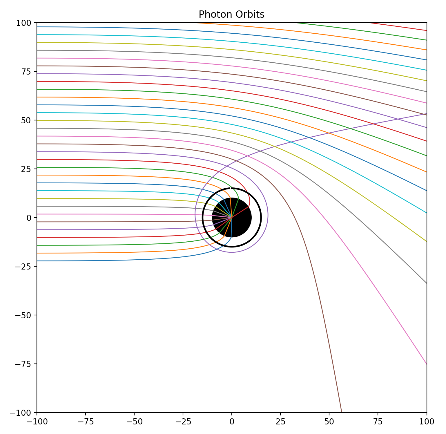
The above diagram [10] shows several photon trajectories as they travel past the black hole. Any ray that travels close enough to the black hole and crosses the event horizon (the black circle, with radius equal to \(r_s\)) becomes trapped, forming the black hole’s “shadow.” Rays outside of this threshold are bent around and may orbit, but do not get trapped in, the black hole. Note that light can orbit multiple times around the black hole, as is the case with one of the purple rays.

The above diagram (one of our own renders!) demonstrates some of the behavior we expect to see when rendering black holes. At the center, we see the Black Hole Shadow, surrounded by a bright photon ring. The photon ring is a region where the black hole’s gravity forces photons into orbits around the event horizon. The Accretion Disk, despite being modeled as a perfectly flat disk, appears above and below the shadow due to light rays curving around the black hole.
The Einstein Ring, represented as the dotted white circle, is the point(s) at which all light rays are perfectly bent such that they hit the same object, creating “rings” of distortion. Objects visible outside of the Einstein Ring have secondary images reflected on the opposite side of the black hole inside the Einstein Ring, such as shown in the two orange circles and the two yellow circles.
The exact mechanisms for studying and tracing light paths in the presence of a black hole require a much deeper study of (and probably a PhD in) theoretical physics, and is quite out of scope for the purposes of this project (especially since our group is lacking in both physics knowledge and PhDs). Below, we present two different approaches for rendering black holes. The first is a (relatively) crude approximation: a simple ray marcher that uses Cartesian coordinates and Forward Euler integration to render Schwarzschild black holes. Then, we build a more physically accurate, generalizable representation using Boyer-Lindquist coordinates and Cash-Karp numerical integration to render either Schwarzschild or Kerr black holes.
Initial Approach: Schwarzschild
Overview: Ray Marching
A Schwarzschild black hole is a simple model for a perfectly symmetric, spherical black hole that has zero charge and zero angular momentum. These assumptions provide a simpler and more well-understood model for light behavior.
Because light rays do not travel in straight paths around a black hole, we can no longer use traditional ray tracing line intersection tests to check for intersections. Instead, we use ray marching, a technique that simulates the (non-linear) path of a light ray by taking small steps through a scene, updating ray parameters where necessary, and computing intersections with the objects the ray encounters along the way.
At any position, we approximate the ray’s acceleration due to gravity with: \(acceleration = -1.5h^2 \frac{\hat{r}}{\|r\|^5}\)
where h is defined as the magnitude of the ray’s specific angular momentum, a constant value calculated once per ray, and r is defined as the vector pointing from the center of the sphere to the photon’s current position. See Appendix A for details and derivations.
Forward Euler Integration
With this acceleration, we can then march rays “backwards” in time using Forward Euler integration, updating the photon’s position and velocity at each time step.
\[curr_position = prev_position + velocity * dt\] \[curr_velocity = prev_velocity + acceleration * dt\]Since our black hole is represented by a sphere centered at the origin, we can test whether a ray has intersected the black hole with the standard geometric ray-sphere intersection between prev_position and curr_position of each ray marching timestep. This yields the following result:

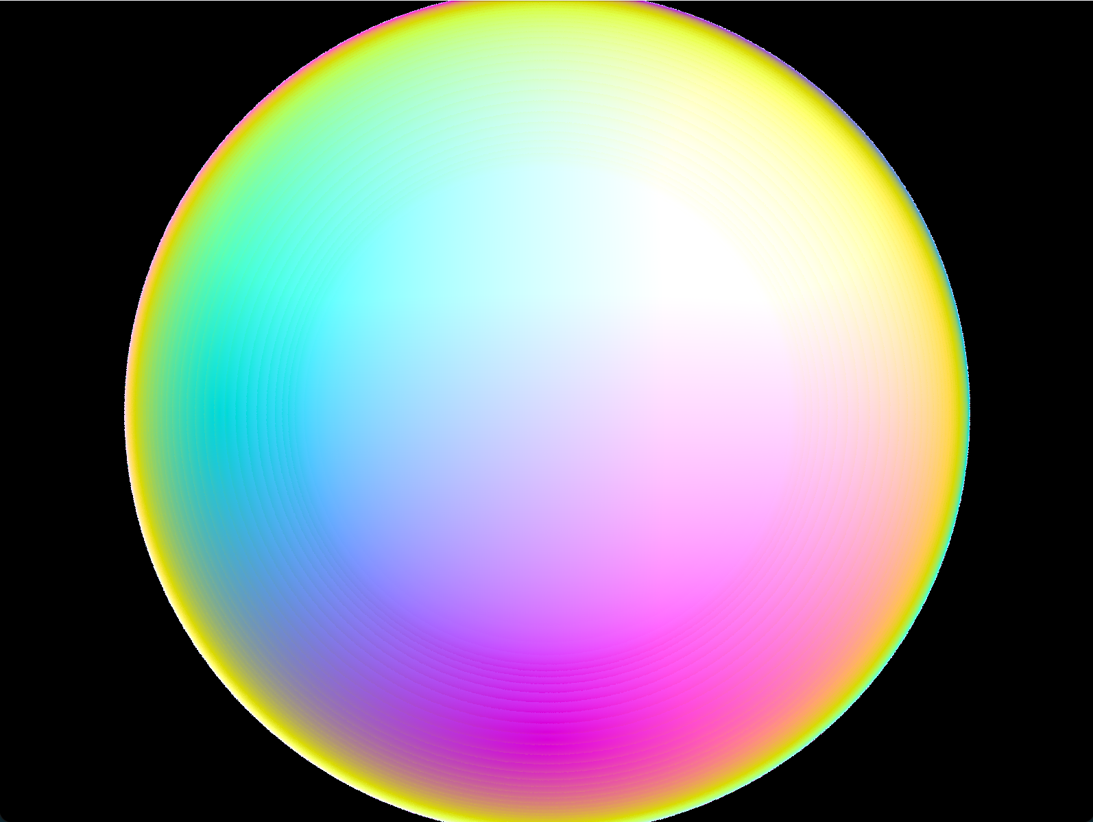
Notable Observations: Since light rays are bent toward the sphere/black hole, the image of the sphere appears bigger as a result. Additionally, this bending of light enables us to see the entire surface of the sphere – we can see colors from the back side of the sphere (yellow and green) along the edges of the image!
We represent the black hole’s accretion disk as a perfectly flat disk with a normal vector (corresponding to the disk’s plane), inner radius, and outer radius (the shape of a 2D donut). Similar to the black hole, we conduct ray-plane intersection at every ray marching timestep; if it intersects the accretion disk plane, we know that the ray intersects the accretion disk itself if the intersection point’s distance from the origin is between the inner and outer radius of the accretion disk.
If the ray has not intersected either the sphere or the accretion disk after taking the maximum number of steps, or the ray travels a sufficiently large distance away from the black hole (ie \(20r_s\)) , we conclude that the ray escapes to infinity; in the physical model, this corresponds to the ray originating from the background (aka the celestial sphere).
Additionally, we implement texture mapping for the black hole surface, accretion disk, and background for debugging as well as preparation for rendering realistic accretion disks and starfield backgrounds. Mapping checkerboard grid patterns provide a helpful visualization for the behavior of light in our render:
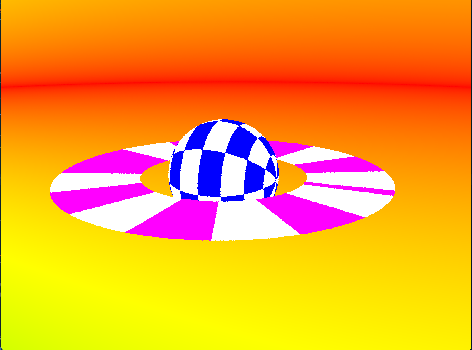
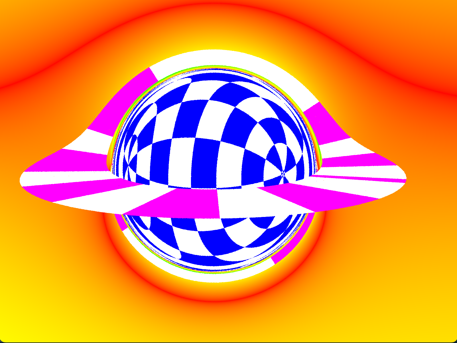
Notable Observations: The accretion disk is represented as a 2D disk, but light curving over/under the black hole causes it to appear in front, on top of, and underneath the black hole. The horizontal red line in the background is distorted and bends over the black hole, while a secondary image is produced below the black hole. Similarly to the previous example, we can see the entirety of the black hole surface, resulting in a denser (blue/white) checkerboard pattern.
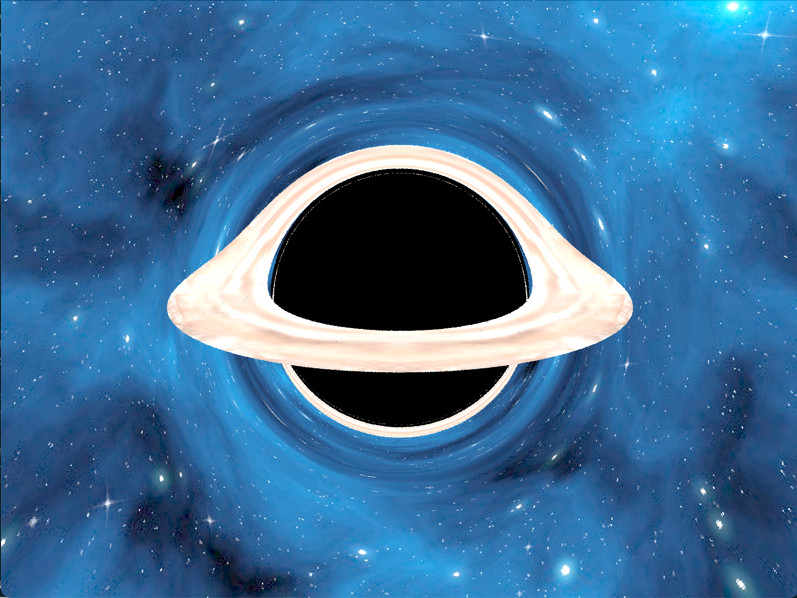
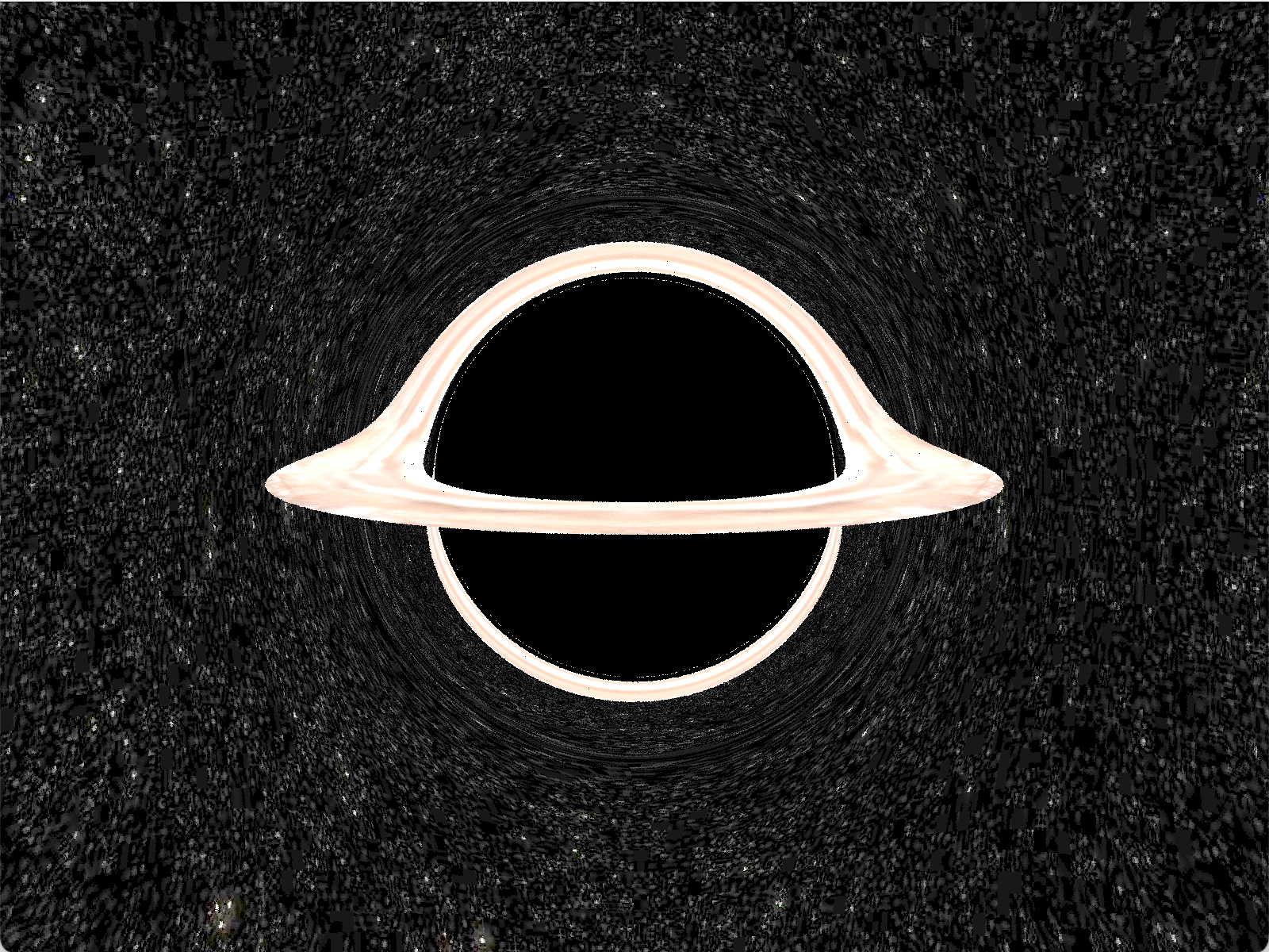
Below, we show two images with proper accretion disk and starfield textures rendered with the above method:
Second Approach: Kerr Black Hole
Overview and Limitations of the previous approach
A Kerr black hole is a more complex model for a black hole that has non-zero angular momentum (but still zero charge). Unfortuantely, the curvature of black hole spacetime means that they cannot be easily or properly represented by Cartesian coordinates. To better account for the physical effects of the black hole’s rotation, we instead use Boyer-Lindquist coordinates, a type of coordinate system used in the theory of general relativity to describe the geometry of spacetime around any rotating massive object (like black holes).
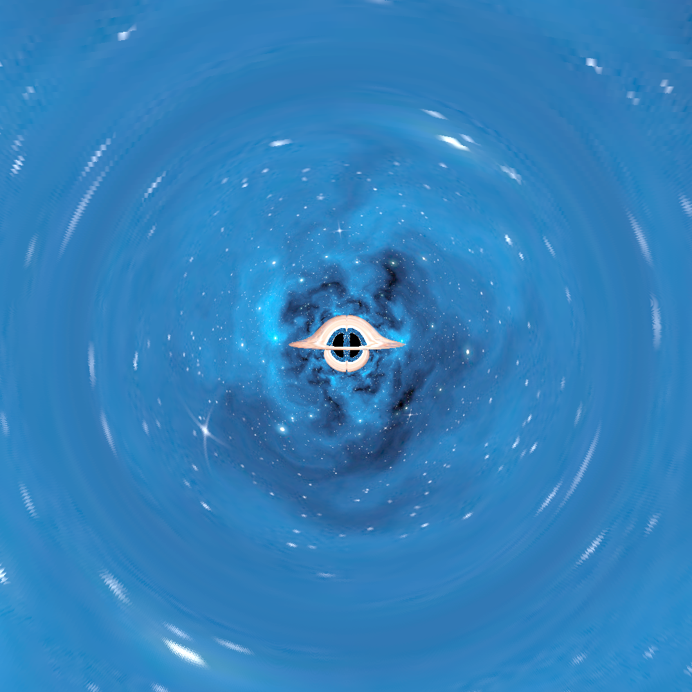
Additionally, the Forward Euler Integration method used in the previous section is potentially unstable and ill-defined. The previous renders required very small step sizes, causing renders to be slow and inefficient. Moreover, moving the camera position far away would sometimes cause our rays to skip portions of or the entire black hole/accretion disk. For example, in the image below, we observe a hole in the center of the black hole:
The methods defined below aim to solve these issues.
Improvements: Boyer-Lindquist
Boyer-Lindquist Coordinates consist of 4 components: \((r, \theta, \phi, t)\). The first 3 coordinates, \((r, \theta, \phi)\), are oblate spherical coordinates. Like in the Schwarzschild case, these coordinates are typically normalized such that the black hole radius is 1. We also have a t-coordinate, which marks the time of an event relative to a distant, unmoving observer. This coordinate system allows us to take into account the asymmetric effect of a black hole’s rotation on spacetime curvature.
Boyer-Lindquist Coordinates can be converted into Cartesian coordinates via:
- \[x = \sqrt(r^2 + a^2) \sin\theta \cos\phi\]
- \[y = \sqrt{r^2 + a^2}\sin{\theta}\sin{\phi}\]
- \[z = r\cos{\theta}\]
The Kerr metric describes the geometry of spacetime around a black hole of mass M and angular momentum J. In Boyer-Lindquist coordinates, distance (the line element) is defined by:
\[ds^2=-\frac{\Delta }{\Sigma }(dt-a sin^2\theta d\phi )^2+\frac{sin^2\theta }{\Sigma}((r^2+a^2)d\phi -adt)^2+\frac{\Sigma }{\Delta }dr^2+ \Sigma d\theta ^2\]- \(\Delta = r^2 - 2 M r + a^2 + Q^2\\): the discriminant for electrical charge
- \[\Sigma = r^2 + a^2 \cos^2(\theta)\]
- \(a = \frac{J}{Mc}\) : Kerr parameter - the ratio between the black hole’s angular momentum and mass. \(a=0\) for non-rotating black holes and \(0 < a < 1\) for rotating black holes.
- As in typical practice, we normalize \(M = 1\).
- Kerr black holes have no electric charge, so \(Q = 0\).
Around a Kerr black hole, a photon follows a null geodesic path, the shortest distance path between two points in curved spacetime. This can be determined by solving a system of differential equations, shown in the table below, where derivatives are taken with respect to propertime \(\tau\). \(p = (p_r, p_{\theta}, p_{\phi}, p_t)\) is the ray’s four-momentum, a generalization of three-dimensional momentum to spacetime. As a convenient convention, we set the ray’s conserved energy, \(-p_t = 1\).
| \(r' = \frac{\Delta}{\Sigma}p_r\) | \(p_r' = \frac{(r - 1) * (-\kappa) + 2r(r^2 + a^2) - 2aL}{\Delta\Sigma} - \frac{2p_r^2(r - 1)}{\Sigma}\) |
| \(\theta ' = \frac{1}{\Sigma}p_{\theta}\) | \(p_{\theta}' = \frac{\sin\theta \cos\theta (\frac{L^2}{a^2} - a^2)}{\Sigma}\) |
| \(\phi ' = \frac{2ar + (\Sigma - 2r)\frac{L}{\sin^2\theta}}{\Delta\Sigma}\) | \(p_{\phi}' = 0\) |
| \(t' = \frac{1 + (2r(r^2 + a^2) - 2arL)}{\Delta\Sigma}\) | \(p_t' = 0\) |
Improvements: Cash-Karp Method
Our ray marching approach for Kerr black holes uses the Cash-Karp method, a fifth-order Runge-Kutta method with an adaptive step size. Cash-Karp is particularly efficient for ODEs with rapidly changing behavior by decreasing step sizes when the solution changes rapidly (such as when we are closer to the black hole), increasing accuracy as well as efficiency.
At each timestep, we integrate forward via Cash-Karp and update our ray’s null geodesic properties. A more complete description of this process is described in Appendix B. Like in our first approach, we perform the following ray-intersection tests:
- If we find that the ray’s r-coordinate is less than the black hole’s event horizon radius, we know that the ray has fallen into the black hole.
- Our accretion disk intersection test remains similar to our first approach; we check if the ray has intersected the accretion disk plane between the disk’s inner and outer radius.
- If the ray’s r-coordinate is greater than the camera’s r-coordinate, or if we have exceeded the max number of steps without intersecting anything, we assume that the ray has escaped to infinity (and map it to a background starfield texture).
Improvements: Texture Mapping of Background and Accretion Disk
For a more realistic accretion disk, we asked an artist friend to create an accretion disk texture for us, pictured here:
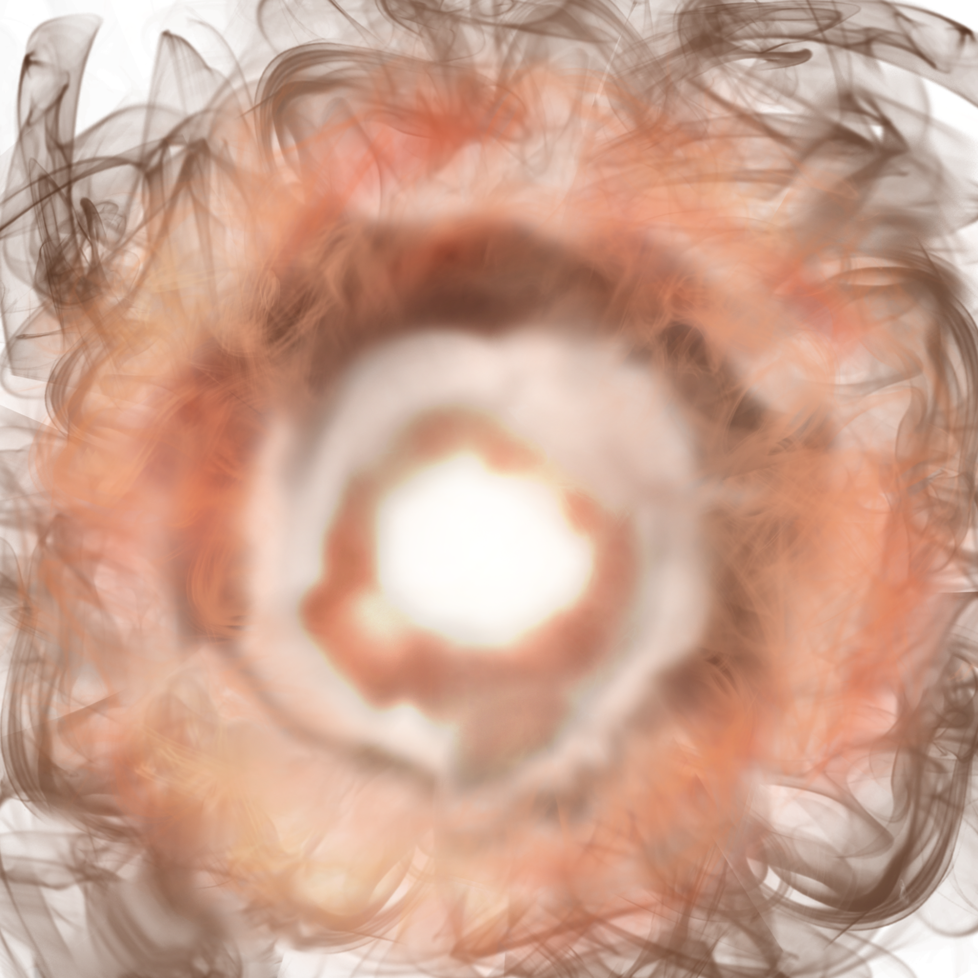
Our custom accretion disk texture includes an alpha-channel, which we use to create semi-transparent feathering of the accretion disk. When a ray intersects the accretion disk during ray-marching, instead of terminating the ray, we march the ray through the accretion disk to also obtain the color of the black hole/background intersection(s) behind it. Then, we linearly interpolate the color of the accretion disk and future intersections with the accretion’s alpha value to achieve the partially transparent effect.
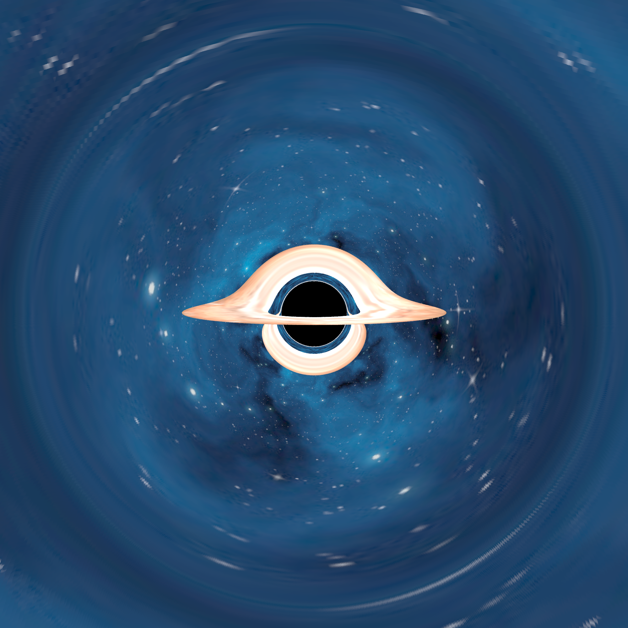
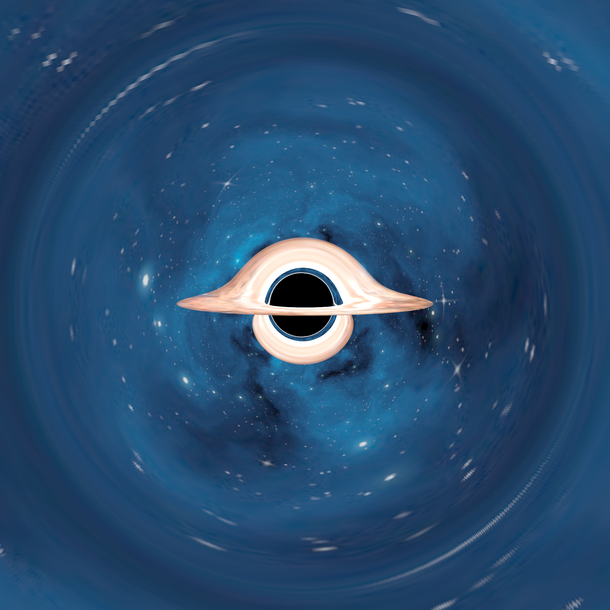
Notable Observations: In the semi-transparent accretion disk render, we can see hints of the blue background and stars showing through the edges of the accretion disk. While subtle, this really contributes to a more realistic look.
Improvements: Bloom Filter Effect
As a post-processing effect, we apply a bloom filter to simulate camera lens flare and brighter intensity of the accretion disk. Bloom also creates a glowing effect where the light of the accretion disk appears to bleed over the edges. After the ray-marching process, we take a square Gaussian kernel and convolve it with each of the pixel colors that belong to the accretion disk. We add this output back to the frame buffer before writing out an image file. Below are images where we gradually increase the intensity of the bloom effect.
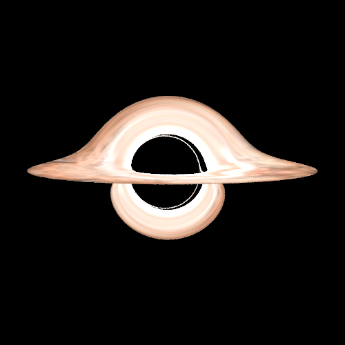
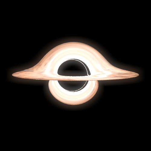
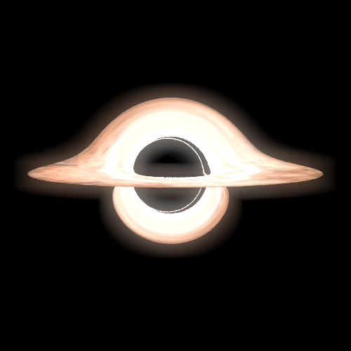
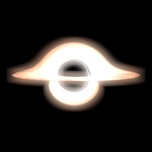
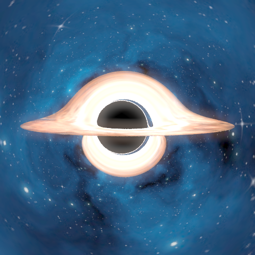
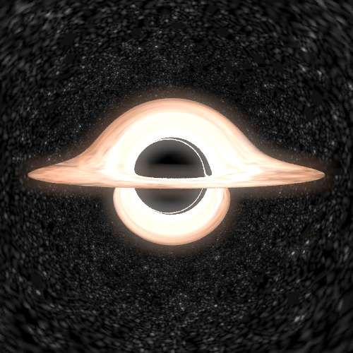
We think that the level of bloom in #3 is the best visually; there is a subtle glowing effect that still showcases the structure of the accretion disk fairly well.
Attempted Improvements: Early Ray Termination Optimization
This paper describes the rendering methods used by DNEG to produce the images of a spinning black hole in the movie Interstellar. Before marching a ray, DNEG uses an early ray termination algorithm that calculates whether or not the ray originates from the black hole’s event horizon; if it does, the ray does not need to be considered further. DNEG only performs numerical integration for rays that originate from the accretion disk or the celestial sphere/starfield background.
We attempted this, but ran into some mathematical bugs that we were unable to resolve in time. Our implementation just integrates all rays, which is slower but should yield similar results. Heavy optimization on our end is less necessary since we did not attempt to create large-scale animations.
Problems Encountered and Lessons Learned
Throughout this project, one of the difficulties we encountered were surrounding the technical approaches of our blackhole implementation. It was difficult to understand physics formulas presented in the paper and parse the heavy mathematical explanations for the existing blackhole models we read about in the references.
We also spend some time understanding the starter code provided by project 3 and project 4. Previously, we treated a lot of the code provided in the starter skeleton as a black box and this project gave us an opportunity to explore how the ray tracing and simulation systems were set up. This understanding influenced our design decisions when setting up the ray-marching infrastructure.
Through this project, we also gained some insights into the nuanced differences between various blackhole models and the ray marching algorithm. Overall, we learned a lot through researching, implementing, and exploring!
Lessons learned: this entire project was one large bug. Haha pain.
Final Results
The two gifs shown below demonstrate the effect of varying the inclination angle of the accretion disk, simulating the effect of a camera orbiting a black hole.
Varying Inclination Angle
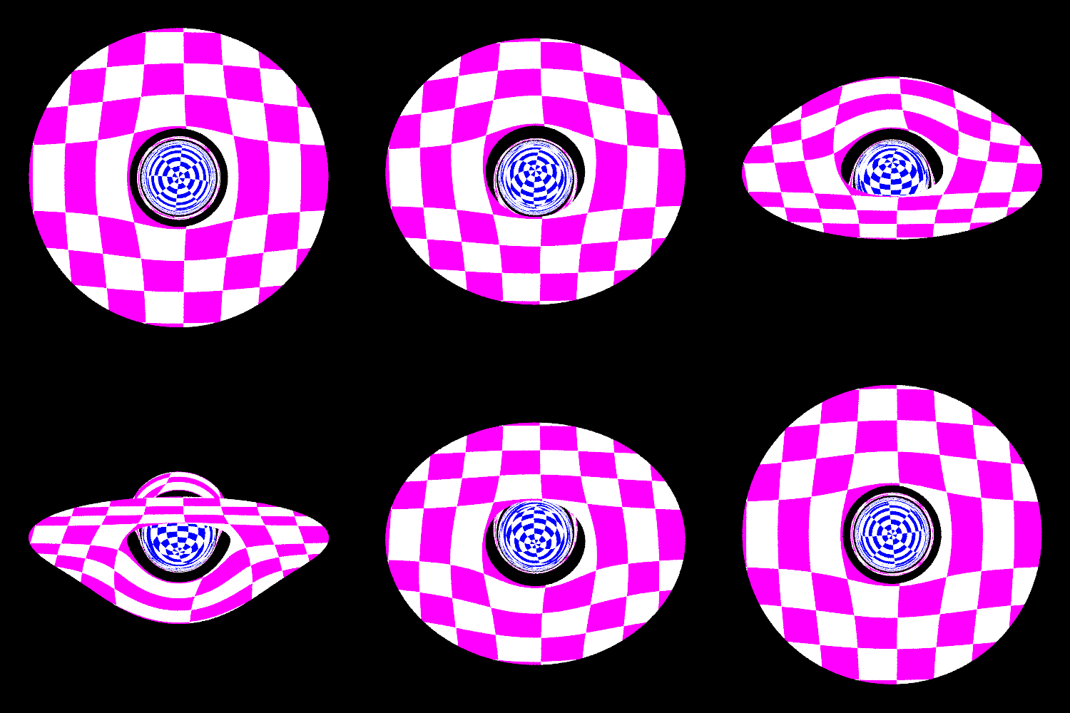
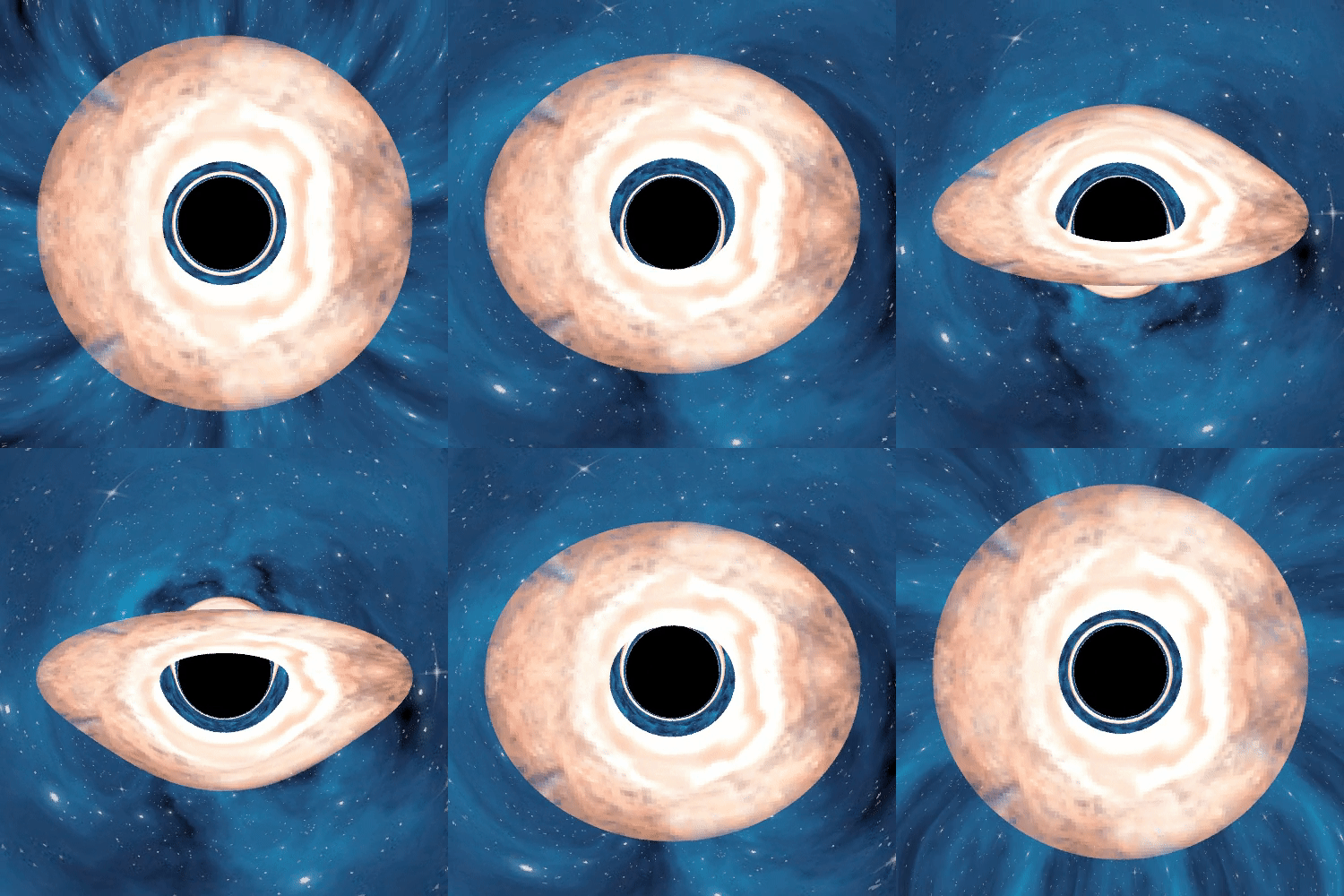
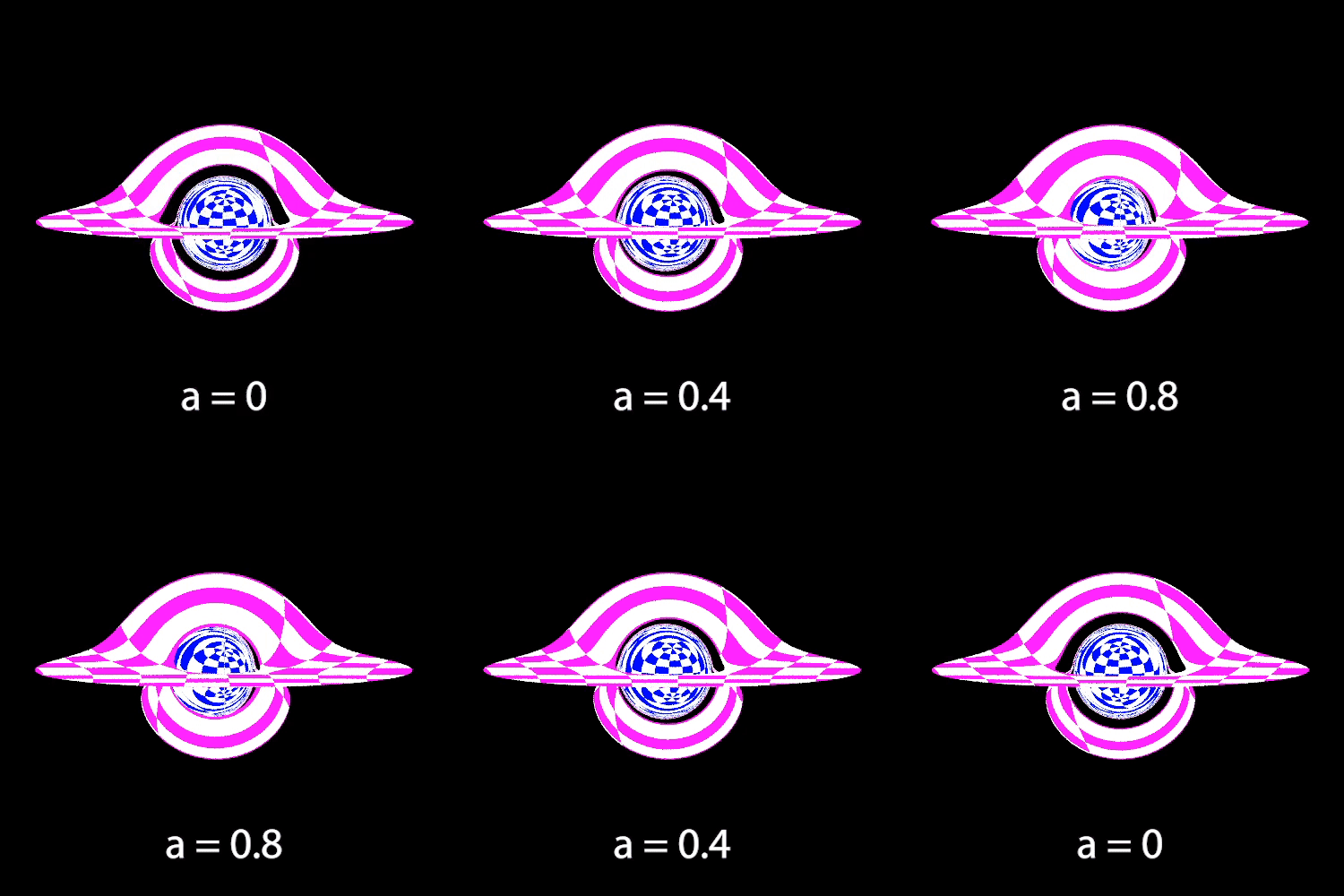
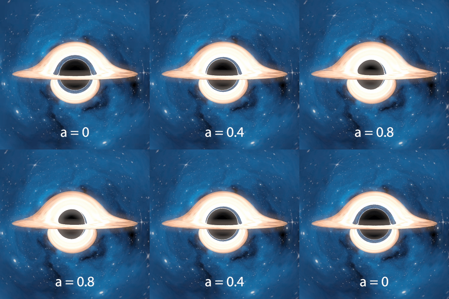
The next two gifs demonstrate the effects of varying the black hole’s angular momentum. We observe changes in the black hole size and asymmetric distortions of both the accretion disk and background.
Varying Angular Momentum
The following 4 images also demonstrate effects of varying the angular momentum, with the camera placed further away from the black hole so that we can see more of the starfield. One more noticeable change is the counterclockwise rotation of images on the Einstein Ring as angular momentum increases.
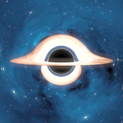
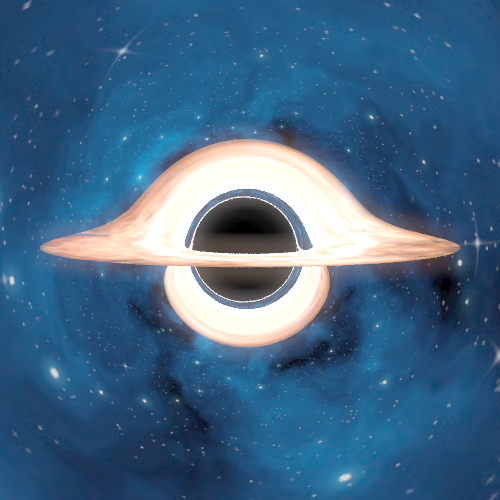
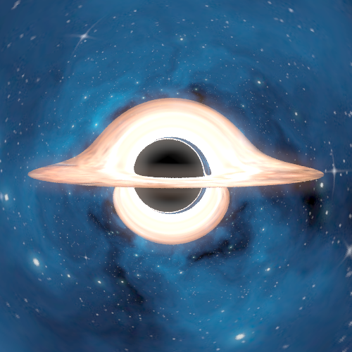
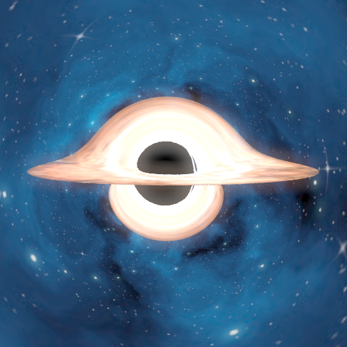
Starfield Accretion Texture Mapping Results
Lastly, we present some large, high-quality renders we produced. These took roughly 6.5 hours each on a 10 core machine:
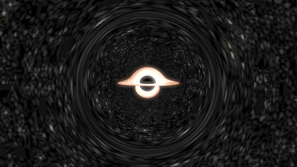
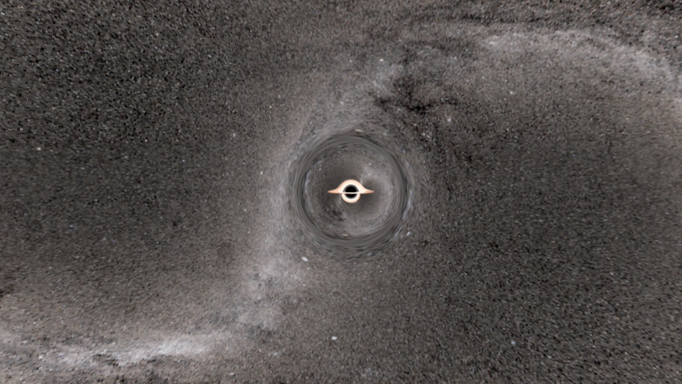
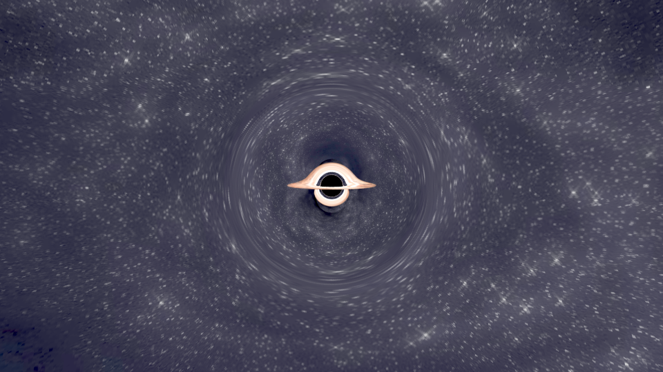
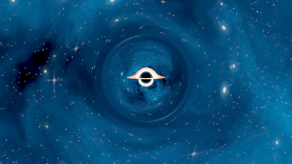
Behold the Infinite
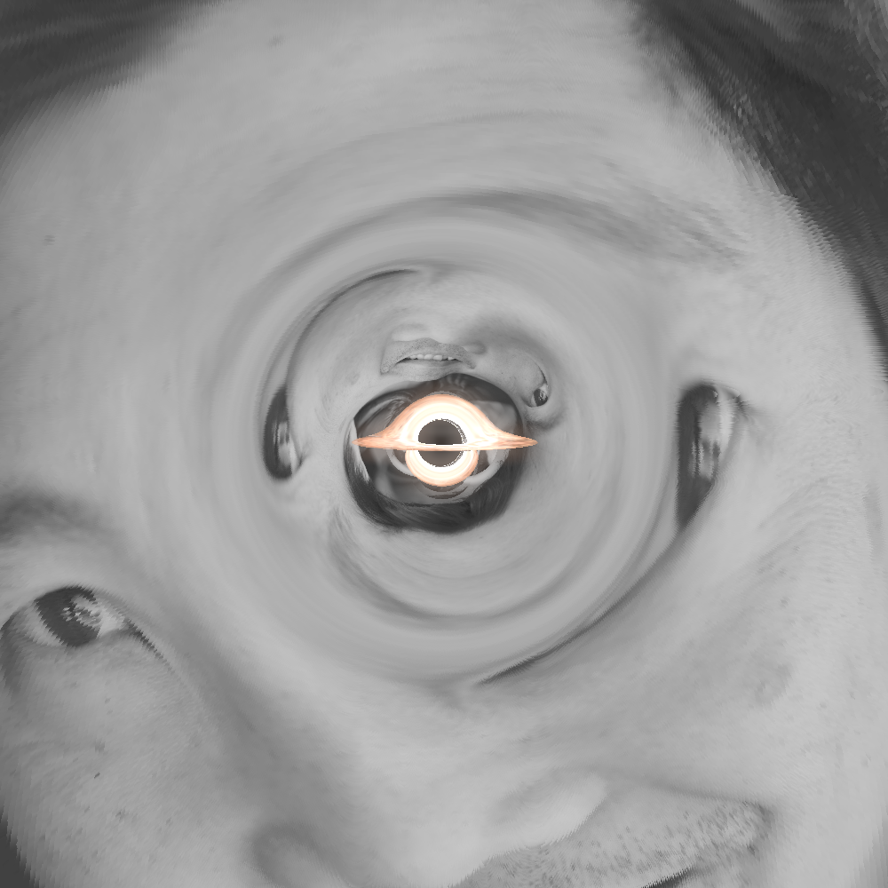
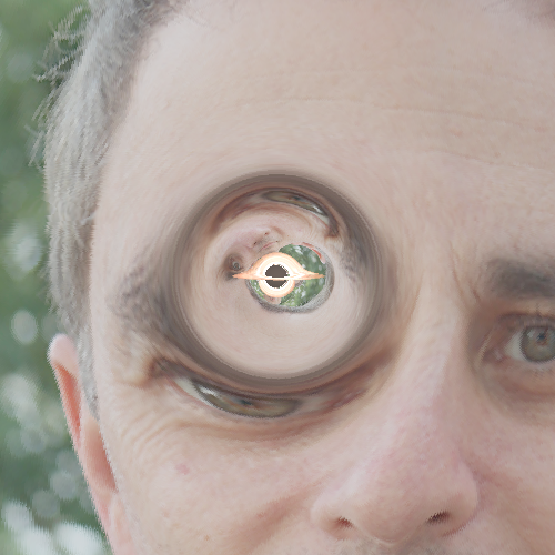
As is standard practice in classes, we are obligated to use the professor’s faces for a meme render. Or perhaps… a RENder:
References
- [1] Interstellar paper: https://iopscience.iop.org/article/10.1088/0264-9381/32/6/065001/pdf
- [2] Bloom shader filter: https://learnopengl.com/Advanced-Lighting/Bloom
- [3] Reference 1: https://rantonels.github.io/starless/
- [4] Reference 2: http://locklessinc.com/articles/raytracing/
- [5] Reference 3: https://www.codeproject.com/Articles/994466/Ray-Tracing-a-Black-Hole-in-Csharp
- [6] Kerr Metric: https://en.wikipedia.org/wiki/Kerr_metric
- [7] Boyer-Lindquist: https://en.wikipedia.org/wiki/Boyer–Lindquist_coordinates
- [8] Cash-Karp method: https://en.wikipedia.org/wiki/Cash–Karp_method
- [9] Runge-Kutta method: https://en.wikipedia.org/wiki/Runge–Kutta_methods
- [10] Ray Diagram: https://galileo-unbound.blog/2019/07/29/orbiting-photons-around-a-black-hole/
Appendix
A: the acceleration derivation
The following derivation was taken from [3]:
For a Schwarzschild Black Hole, the angular momentum \(a = 0\) and charge \(Q = 0\). Additionally, we normalize the speed of light \(c = 1\) and the black hole’s Schwarzchild radius \(r_s = 1\). Therefore, the line element (in spherical coordinates) can be defined as: \(ds^2 = (1 - \frac{1}{r})dt^2 - (1 - \frac{1}{r})^{-1}dr^2 - r^2d\theta^2 - r^2\sin^2\theta d\phi^2\)
We set \(\theta = \frac{\pi}{2}\), so \(d\theta = 0\). Additionally, we define \(e = (1 - \frac{1}{r})\frac{dt}{d\tau}\) and \(l = r^2 \frac{d\phi}{d\tau}\), and then set \(ds^2 = 1\). \((1 - \frac{1}{r})dt^2 - (1 - \frac{1}{r})^{-1}dr^2 - r^2d\theta^2 - r^2\sin^2\theta d\phi^2 = 1\) \(\frac{1}{1 - \frac{1}{r}} * e^2 - \frac{1}{1 - \frac{1}{r}}\frac{dr^2}{d\tau^2} - r^2 * 0 - \frac{l^2}{r^2} = 1\) \(\frac{1}{1 - \frac{1}{r}}\frac{dr^2}{d\tau^2} = \frac{1}{1 - \frac{1}{r}} * e^2 - 1 - \frac{l^2}{r^2}\) \(\frac{dr^2}{d\tau^2} = e^2 - (1 - \frac{1}{r}) (1 + \frac{l^2}{r^2})\) \(r^4 \frac{dr^2}{d\tau^2} = r^4 \frac{dr^2}{d\phi^2}\frac{d\phi^2}{d\tau^2} = l^2 \frac{dr^2}{d\phi^2} = r^4 e^2 - (1 - \frac{1}{r}) (r^4 + r^2l^2)\) \(\frac{dr^2}{d\phi^2} = \frac{r^4 e^2}{l^2} - (1 - \frac{1}{r}) (\frac{r^4}{l^2} + r^2)\)
We then perform the change of coordinates \(r \implies u = \frac{1}{r}\), yielding: \(\frac{du^2}{d\phi^2} = \frac{1}{b^2} - (1 - u) (a^{-2} + u^2)\) where \(b = \frac{l}{e}\) and \(a = l\)
We take \(\lim_{a \to \inf}\), so \(\frac{du^2}{d\phi^2} = \frac{1}{b^2} - (1 - u) (u^2)\)
This equation can then be solved to yield: \(u^{''}(\phi) = -u (1 - \frac{3}{2} u^2)\), or \(u^{''}(\phi) + u = \frac{3}{2} u^3\).
The Binet equation for the equation for orbit of a particle is \(u^{''} + u = - \frac{1}{mh^2u^2}F(u)\)
By setting \(m = 1\), equating the above two equations, and plugging back in \(r = \frac{1}{u}\), we obtain: \(F = a = -\frac{3}{2}h^2\frac{\hat{r}}{r^5}\), which we can use for ray marching.
B: Cash-Karp Integration
The Cash-Karp method is a type of Runge-Kutta method (the same family as Forward Euler Integration), which approximate the solution of an ODE by iteratively computing a sequence of intermediate values that depend on the previous values and the derivatives of the function at those values. Cash-Karp is a fifth order method, and estimates/integrates forward via: \(y_{n+1} = y_n + h \sum_{i=1}^s b_i k_i\) where:
- \[k_1 = f(t_n, y_n)\]
- \[k_2 = f(t_n + \frac{1}{5}*h, y_n + \frac{1}{5}k_1*h)\]
- \[k_3 = f(t_n + \frac{3}{10}*h, y_n + (\frac{3}{40}k_1 + \frac{9}{40}k_2)*h)\]
- \[k_4 = f(t_n + \frac{3}{5}*h, y_n + (\frac{3}{10}k_1 - \frac{9}{10}k_2 + \frac{6}{5}k_3)*h)\]
- \[k_5 = f(t_n + h, y_n + (\frac{-11}{54}k_1 - \frac{5}{2}k_2 + \frac{-70}{27}k_3 + \frac{35}{27}k_4)*h)\]
- \[k_6 = f(t_n + \frac{7}{8} h, y_n + (\frac{1631}{55296}k_1 - \frac{175}{512}k_2 + \frac{575}{13824}k_3 + \frac{44275}{110592}k_4 + \frac{253}{4096}k_5)*h)\]
- \[b_1 = \frac{37}{378}\]
- \[b_2 = 0\]
- \[b_3 = \frac{250}{621}\]
- \[b_4 = \frac{125}{594}\]
- \[b_5 = 0\]
- \[b_6 = \frac{512}{1771}\]
Additionally, Cash-Karp includes a sixth-order estimate to estimate the error of the fifth order solution. For every timestep, if the error estimate is too large, then Cash-Karp reduces the step size until the error is below some threshold. Error is calculated via \(e_{n+1} = y_{n+1} - y_{n+1}^* = h \Sigma_{i=1}^s(b_i - b_i^*)k_i\), where:
- \[y_{n+1}^* = y_n + h \Sigma_{i=1}^sb_i^*k_i\]
- \[b_1^* = \frac{2825}{27648}\]
- \[b_2^* = 0\]
- \[b_3^* = \frac{18575}{48384}\]
- \[b_4^* = \frac{13525}{55296}\]
- \[b_5^* = \frac{277}{14336}\]
- \[b_6^* = \frac{1}{4}\]
Cash-Karp is advantageous because it allows for high accuracy and efficiency due to its adaptive step size control. In our application, this allows us to take large step sizes while far away from the black hole (where the effect of gravitational lensing is less apparent) and smaller step sizes while close to the black hole, where photon trajectories change drastically.
C: Bug Art Gallery


